Camera placement changes the result
Software tuning cannot rescue poor physical geometry. Elevation, lateral alignment, optical shielding, and homography mapping set the ceiling on how accurately any intelligent controller reads the field.
Height, setback, and the occlusion problem
When a camera sits near eye level on a touchline tripod, athletes in the foreground constantly block players and the ball on the far side of the field. Computer-vision detectors see overlapping silhouettes merge into one blob, causing the tracking box to drift toward the nearest stationary defender rather than the ball carrier behind them.
Raising the lens to a balcony, press gantry, or temporary 6-to-10-meter telescopic mast opens vertical separation between players across depth lanes. A setback of 5 to 12 meters behind the touchline is equally important: it keeps the pan angles gentle when play hugs the near sideline, preventing violent 90-degree whip pans as a winger sprints past the camera base.
Centering the mount directly on the halfway line (or mid-court line) simplifies both perspective distortion and automated zoom scaling. Asymmetric placement off toward one corner forces the controller to calculate steeper depth ratios on one half than the other, often leaving the far goal area undersized.
Homography mapping and exclusion masks
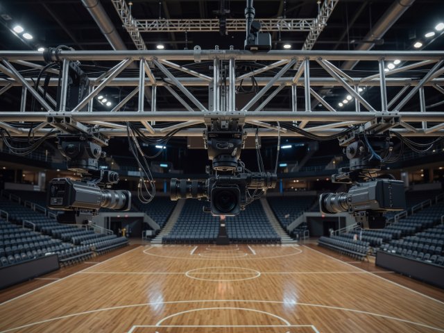
Before an automated controller can frame accurately, it needs to know where the legal playing surface begins and ends in 3D space. During setup, an engineer marks four or more known court intersections—corner flags, penalty arc vertices, center circle tangents, or basketball key corners—to build a homography transformation between 2D sensor pixels and real-world pitch meters.
Accurate pitch mapping delivers two immediate benefits. First, it teaches the zoom algorithm true physical distance: a 25-meter wide box looks identical in pixels whether play sits on the near wing or far touchline. Second, it enables strict exclusion masks that instruct the detector to ignore warm-up zones, team benches, referee assistants, and adjacent training pitches—eliminating the classic failure mode where a spare ball kicked behind the goal pulls the broadcast camera away from live play.
Lighting stability, shutter speed, and LED boards
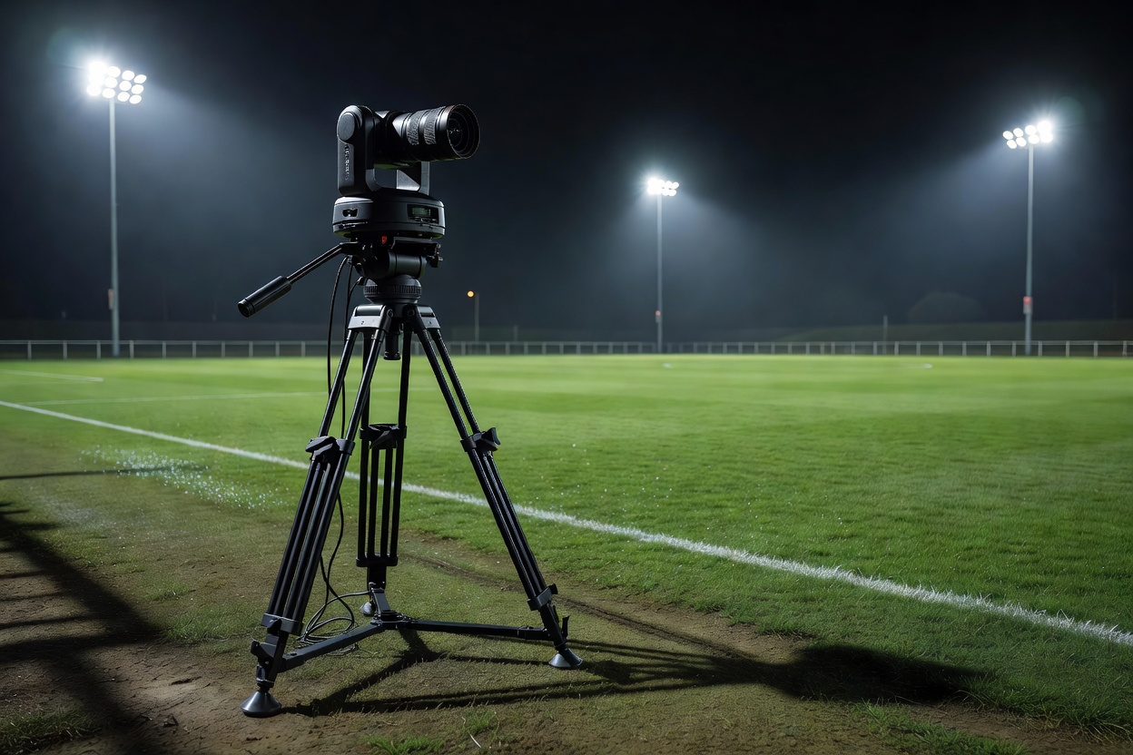
Municipal stadiums and multi-sport halls often use older metal-halide lamps or pulse-width-modulated (PWM) LED luminaires that flicker at 100 Hz or 120 Hz, alongside perimeter LED advertising boards cycling bright white graphics. High-contrast flicker disrupts frame-to-frame object tracking and creates rolling horizontal bands in CMOS sensors.
Locking exposure manually—rather than leaving iris and ISO on auto—prevents sudden brightness jumps whenever a player runs across a white sponsor graphic or into a shadowed corner. Aim for a fixed shutter speed between 1/250s and 1/500s (synchronized to mains frequency multiples when LED banding appears), disable auto white balance so turf colors remain consistent across pans, and fit deep matte lens hoods whenever floodlights sit within 25 degrees of the optical axis.
Pre-match venue calibration checklist
Run these six physical and software checks at least 45 minutes before warm-up completes.
Calibration sets the baseline; human oversight handles the unexpected.
Even on a perfectly mapped pitch, weather shifts, player injuries, and split-second tactical restarts demand a clear intervention protocol.
Next: Operator Oversight & Recovery